New Arrivals
-
Sale!
 New
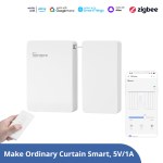
NewSONOFF Smart Roller Shutter Switch | MINI-RBS
Price range: USD$17.90 through USD$52.90 Select options This product has multiple variants. The options may be chosen on the product page -
 New
NewSONOFF iPlug Zigbee Smart Plug | S60 Series
USD$13.50 Select options This product has multiple variants. The options may be chosen on the product page -
 New
NewSONOFF IP65 Zigbee LCD Smart Temperature Humidity Sensor | SNZB-02WD
USD$17.90 Add to cart -
 New
NewSONOFF SNZB-02LD IP65 Zigbee LCD Smart Thermometer (Probe Version)
USD$17.90 Add to cart -
 New
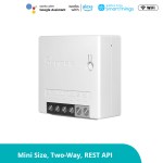
NewSONOFF MINI Dry Wi-Fi Smart Switch | MINI-D
USD$12.90 Add to cart
Best Seller
-
 -10%
-10%SONOFF iHost Smart Home Hub
Price range: USD$99.90 through USD$129.90 Select options This product has multiple variants. The options may be chosen on the product page
Smart Home
DIY Smart Switches
Smart Plugs & Wall Switches
Smart Lighting
Smart Home Security
View All >>
-

SONOFF MINI Extreme Wi-Fi Smart Switch MINIR4
USD$9.90 Add to cart -
Sale!
 -20%
-20%SONOFF NSPanel Smart Scene Wall Switch(86/EU Type/120 Type)
Price range: USD$59.90 through USD$108.00 Select options This product has multiple variants. The options may be chosen on the product page -

SONOFF Zigbee Wireless Switch | SNZB-01P
USD$9.90 Add to cart
-

SONOFF DUALR3/DUALR3 Lite Dual Relay Two Way Power Metering Smart Switch
Price range: USD$12.40 through USD$13.98 Select options This product has multiple variants. The options may be chosen on the product page -

SONOFF L3 Pro RGBIC Smart LED Strip Lights-5M/16.4Ft
USD$26.99 Add to cart -
Sale!
 -20%
-20%SONOFF Zigbee Bridge Pro
Original price was: USD$24.90.USD$19.90Current price is: USD$19.90. Add to cart -

SONOFF TH Elite Smart Temperature and Humidity Monitoring Switch
Price range: USD$16.99 through USD$19.99 Select options This product has multiple variants. The options may be chosen on the product page -

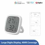
SONOFF SNZB-02D Zigbee LCD Smart Temperature Humidity Sensor
USD$12.99 Add to cart -

SONOFF TX Ultimate Smart Touch Wall Switch
Price range: USD$24.90 through USD$32.90 Select options This product has multiple variants. The options may be chosen on the product page -

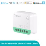
SONOFF MINI Extreme Wi-Fi Smart Switch (Matter-enabled)
USD$12.90 Add to cart -

SONOFF iPlug Wi-Fi Smart Plug | S60 Series
USD$10.90 Select options This product has multiple variants. The options may be chosen on the product page -

SONOFF Zigbee Motion Sensor | SNZB-03P
USD$11.90 Add to cart -
 New
NewSONOFF SwitchMan Smart Wall Switch-M5 Matter (White)
Price range: USD$17.99 through USD$22.49 Select options This product has multiple variants. The options may be chosen on the product page -
 New
NewSONOFF Micro Zigbee USB Smart Adaptor
USD$12.90 Add to cart -

SONOFF Zigbee Bridge Ultra
USD$69.90 Add to cart
-

SONOFF DUALR3/DUALR3 Lite Dual Relay Two Way Power Metering Smart Switch
Price range: USD$12.40 through USD$13.98 Select options This product has multiple variants. The options may be chosen on the product page -
Sale!
 -20%
-20%SONOFF NSPanel Smart Scene Wall Switch(86/EU Type/120 Type)
Price range: USD$59.90 through USD$108.00 Select options This product has multiple variants. The options may be chosen on the product page -

SONOFF L3 Pro RGBIC Smart LED Strip Lights-5M/16.4Ft
USD$26.99 Add to cart -
Sale!
 -20%
-20%SONOFF Zigbee Bridge Pro
Original price was: USD$24.90.USD$19.90Current price is: USD$19.90. Add to cart -

SONOFF TH Elite Smart Temperature and Humidity Monitoring Switch
Price range: USD$16.99 through USD$19.99 Select options This product has multiple variants. The options may be chosen on the product page -

SONOFF SNZB-02D Zigbee LCD Smart Temperature Humidity Sensor
USD$12.99 Add to cart -

SONOFF MINI Extreme Wi-Fi Smart Switch MINIR4
USD$9.90 Add to cart -

SONOFF TX Ultimate Smart Touch Wall Switch
Price range: USD$24.90 through USD$32.90 Select options This product has multiple variants. The options may be chosen on the product page -

SONOFF MINI Extreme Wi-Fi Smart Switch (Matter-enabled)
USD$12.90 Add to cart -

SONOFF Zigbee Wireless Switch | SNZB-01P
USD$9.90 Add to cart -

SONOFF iPlug Wi-Fi Smart Plug | S60 Series
USD$10.90 Select options This product has multiple variants. The options may be chosen on the product page -

SONOFF Zigbee Motion Sensor | SNZB-03P
USD$11.90 Add to cart
Nextion Display
Edge Series
Discovery Series
Enhanced Series
Intelligent Series
View All >>
-

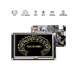
4.3” Nextion Intelligent Series HMI Touch Display with enclosure
Price range: USD$52.90 through USD$59.90 Select options This product has multiple variants. The options may be chosen on the product page -

4.3” Nextion Intelligent Series HMI Touch Display
Price range: USD$46.90 through USD$54.90 Select options This product has multiple variants. The options may be chosen on the product page -

5.0” Nextion Intelligent Series HMI Touch Display with enclosure
Price range: USD$67.90 through USD$74.90 Select options This product has multiple variants. The options may be chosen on the product page
-

NX3224T024 – Nextion 2.4” Basic Series HMI Touch Display
USD$22.90 Add to cart -

NX3224T028 – Nextion 2.8” Basic Series HMI Touch Display
USD$25.40 Add to cart -

NX4832T035 – Nextion 3.5” Basic Series HMI Touch Display
USD$39.90 Add to cart -

NX4827T043 – Nextion 4.3” Basic Series HMI Touch Display
USD$54.90 Select options This product has multiple variants. The options may be chosen on the product page -

NX8048T050 – Nextion 5.0” Basic Series HMI Touch Display
USD$71.90 Add to cart -

NX8048T070 – Nextion 7.0” Basic Series HMI Touch Display
USD$89.90 Add to cart -

NX3224K024 – Nextion 2.4” Enhanced Series HMI Touch Display
USD$22.90 Add to cart -

NX3224K028 – Nextion 2.8” Enhanced Series HMI Touch Display
USD$25.40 Add to cart
-

4.3” Nextion Intelligent Series HMI Touch Display with enclosure
Price range: USD$52.90 through USD$59.90 Select options This product has multiple variants. The options may be chosen on the product page -

4.3” Nextion Intelligent Series HMI Touch Display
Price range: USD$46.90 through USD$54.90 Select options This product has multiple variants. The options may be chosen on the product page -

5.0” Nextion Intelligent Series HMI Touch Display with enclosure
Price range: USD$67.90 through USD$74.90 Select options This product has multiple variants. The options may be chosen on the product page -

5.0” Nextion Intelligent Series HMI Touch Display
Price range: USD$63.90 through USD$71.90 Select options This product has multiple variants. The options may be chosen on the product page -

7.0” Nextion Intelligent Series HMI Touch Display with enclosure
Price range: USD$89.90 through USD$102.40 Select options This product has multiple variants. The options may be chosen on the product page -

10.1” Nextion Intelligent Series HMI Touch Display
Price range: USD$124.00 through USD$134.00 Select options This product has multiple variants. The options may be chosen on the product page
Airspy
High Quality Approach to Software-Defined Radio
carousel title
from 2839 reviews
QUALITY AND SAVING
Manufacturer direct

SECURE PAYMENT
Safe & Trustworthy

Fast Delivery
Global partner of Special Line& DHL

Friendly Services
Quick customer support & services


